How to Measure Conduit Runs on Digital Plans for Takeoffs
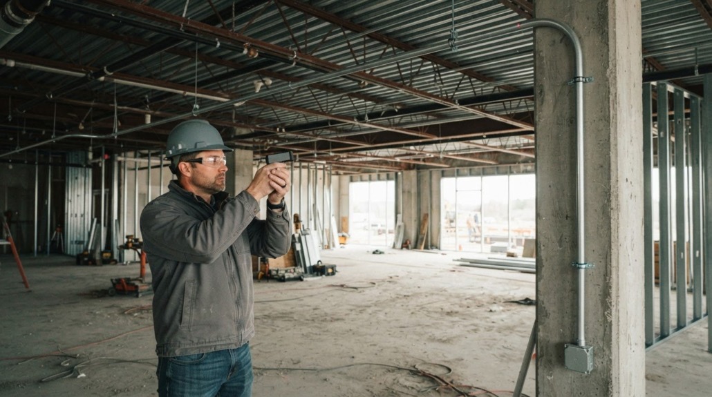
Measure horizontal conduit runs at right angles to building lines, and calibrate your digital takeoff software to the drawing scale before tracing. This provides a consistent starting point for measuring conduit runs on digital plans. Include vertical sections in the route total instead of treating the plan view as the entire run.
Accurate digital measurements depend on reading the drawings carefully. A route may cross rooms, rise between levels, or shift around other building systems, so a quick trace can miss details that affect the takeoff. Follow a consistent process: set the scale, trace horizontal runs, account for vertical sections and fittings, then compare the measurements with the drawings and specifications.
Digital takeoff tools can help organize lengths and review results. The goal is a conduit quantity you can explain and verify, not merely a line traced on screen.
Key Takeaways
- Calibrate the digital plan to its stated scale before tracing routes, then measure horizontal runs at right angles to building lines.
- Include vertical rises and drops in each route total, and use an isometric sketch to clarify transitions that a plan view can hide.
- Use takeoff tools to connect conduit segments and fittings, then review the measured-element count for gaps.
- Compare takeoff quantities with plan symbols, schedules, and specifications so conduit sizes, routes, and termination allowances align.
- Review bends and routing against the surrounding systems before finalizing quantities; a clear route is easier to measure and coordinate.
Accounting for vertical conduit runs
Identify fittings, boxes, and supports by their plan symbols, then check them against schedules and details. Include fitting lengths in the route total, but track support quantities separately from conduit length.
- Trace each rise and drop. Follow the conduit path between floors, ceilings, equipment, and boxes. Compare the plan view with elevations and riser diagrams, since a vertical section may not appear as a measurable line in plan view. Mark each transition where the route leaves one level and reaches another. An isometric sketch with accurate dimensions can clarify the complete path before you total it.
- Measure the vertical distance between levels. Use the elevations shown on the drawings to determine the rise or drop between connection points. Record each segment separately, then add those measurements to the horizontal route. If a floor slopes, a laser measuring tool can help establish the distance between points, including from a level reference 22 feet above. Keep the reference point and measured endpoints clear in your takeoff notes.
- Calculate offsets and include bends. For a 30-degree conduit offset, multiply the required offset distance by 2. For a 10-degree offset, multiply it by 6. Apply the multiplier to the offset distance shown by the geometry, then record the resulting conduit length. Include bends in the route review, not just the straight rise. Most electrical codes, including the NEC in the United States, limit total conduit-run bending to 360°.
- Count route fittings, boxes, and supports. Read plan symbols alongside schedules and detail callouts to identify the fittings and boxes connected to each vertical path. Add fitting lengths when the takeoff method accounts for them separately from straight segments. Count supports from the locations or spacing shown in project documents, and list them as items rather than adding them to linear footage. A folding rule can help with physical measurements where digital drawings lack a clear dimension.
- Review the route before totaling it. Compare the rise, offsets, fittings, and endpoints against the plan, elevation, and specifications. Check that the sketched path avoids blocking other construction installations. Keep bends as few as practical, and note any route that changes direction between levels. For exposed conduit, corners and other linear building features can provide a clear route reference. Separate measured dimensions from assumptions, so another estimator can follow each quantity.
Digital takeoff software and mobile tools
Digital takeoffs measure routes from calibrated drawings, while field measurements reflect installed conditions. Compare the two when site conditions or drawing revisions affect the route.
Calibrate the Plan Scale
Set the digital takeoff software to the drawing’s stated scale before tracing. Use a known dimension on the sheet as a reference, then compare the software measurement with it. If they differ, recalibrate before measuring conduit.
Check each sheet separately because plan sets may use different scales. Correct calibration gives every later measurement a dependable drawing-based reference.
Measure Distances with Digital Tools
Select the conduit path and trace its visible segments in sequence. A takeoff tool may identify connected elements after you select a segment. Measure the straight sections, then review the route for fittings and transitions.
Measure ConduitRun automatically includes straight conduit segments and fitting lengths in its total. Since straight segments need no parameter configuration, focus your review on connected fittings and route continuity.
- Use a phone or tablet to review plan details near the work area, if your workflow supports mobile drawing access. Zoom in on congested areas, compare symbols with the full plan, and record questions for the estimate review. Avoid treating a small screen view as a substitute for the calibrated drawing. Accura Cadd PDF Draw is an on-screen takeoff option for reviewing electrical plans; explore electrical estimating tools when choosing a digital workflow.
Compare Takeoff Accuracy with Field Measurements
Compare drawing totals with field measurements when a route is already installed or site conditions change its path. Check that both measurements use the same endpoints, and account for every turn before assessing differences. A digital result follows the plan geometry; a field result reflects the route measured on site. If they differ, determine whether the drawing, scale, endpoints, or installed path explains the gap.
- Review the software’s measured-element count before accepting the total. Measure ConduitRun reports the number of elements measured successfully, which can reveal incomplete parameter coverage. Compare that count with the connected route shown on the plan. If a fitting or segment is missing, adjust its parameters and recalculate. Keep the drawing measurement, field check, and any adjustment visible in your takeoff notes.
Measuring horizontal conduit runs
Trace each horizontal route along the drawing, measuring at right angles to building lines. This helps prevent diagonal shortcuts and missed turns from distorting the takeoff.
Trace Horizontal Conduit Runs
Start at the first connection point and follow the conduit to its endpoint. Measure each horizontal leg at right angles to building lines. When measuring conduit runs on digital plans, follow the route rather than drawing a shortcut across a room.
For example, measure each leg around a room corner separately. Mark every turn as you trace so it remains visible in the total.
- Separate route segments from plan symbols. Follow the linework representing conduit, distinguishing it from walls, reference lines, and other electrical symbols. A line crossing a room does not necessarily mean conduit follows its full length. Check nearby labels and connection points. Where the route meets a box or equipment symbol, record that endpoint before tracing onward. This helps keep separate runs from blending into one measurement.
- Break complex paths into measurable legs. Divide a route at each turn, branch, or change in direction. Measure each straight leg separately, then add the segment lengths for the route total. A path along one wall, across a corridor, and beside another wall has three distinct legs. Recording them separately makes review easier and helps show where a measurement difference may have entered the takeoff.
Check for Measurement Mistakes and Risks
Review each marked route against the drawing before accepting its total. Check for diagonal shortcuts, missed turns, duplicated branches, and endpoints that stop short of connection symbols. Compare the conduit path with nearby building systems to ensure the route does not block or impede them.
If plan lines overlap, zoom in and inspect their labels and endpoints. Use drawing details to resolve crossings instead of assuming they indicate connections.
- Record the route clearly for review. Keep every measured run identifiable by its starting point, endpoint, and direction changes. Use labels or separate takeoff groups for routes serving different equipment or areas. For measuring conduit runs on digital plans, clear route notes make it easier to retrace the path during review. Compare the traced route with related electrical plan details. If a revision changes a wall, endpoint, or route, update the affected legs rather than unrelated totals.

How to calibrate scale and measure distances in digital plan takeoff software
- Open the correct drawing sheet. Match its title and revision to the electrical plan set. Digital files may include sheets at different scales, so do not assume one setting applies everywhere. Find a printed scale or dimension on the active sheet. Use that reference before tracing conduit, and identify the sheet in your takeoff records.
- Choose a clear calibration reference. Select a dimensioned line with visible endpoints, such as a wall segment or grid spacing. Avoid a fuzzy label, broken line, or measurement crossing several symbols. In the software, mark both endpoints carefully and enter the dimension exactly as shown. This links the screen distance to the drawing’s stated measurement.
- Confirm the measurement units. Match the software units to the drawing’s units before saving the calibration. A mismatch can make every traced conduit length incorrect, even when the screen line follows the route accurately. Check the dimension label against the takeoff display. If the displayed reference does not match the plan dimension, correct the units or recalibrate.
- Test the scale against another reference. Measure a separate dimension on the same sheet, preferably in another area. Compare the software result with the printed value before tracing longer routes. If the measurements disagree, inspect the selected endpoints and calibration line. Recalibrate with a clearer reference, then test again. Do not use a questionable scale for conduit quantities.
- Measure one route segment at a time. Start at a clear connection point, trace the conduit line, and stop at its next turn or endpoint. Keep separate legs distinct, especially where a route branches or crosses another line. Review the displayed length before adding another segment. This makes missed turns and accidental shortcuts easier to spot during takeoff review.
- Save the calibration and record its scope. Note the sheet, revision, scale, and units alongside the takeoff. If another sheet uses a different scale, calibrate it separately. After a drawing revision, compare the changed sheet and check the scale again before measuring affected routes. A concise record lets another estimator retrace the reference and understand which drawing informed each quantity.
Once calibration is confirmed, follow a consistent sequence: begin electrical takeoffs with lighting and finish with service runs. This gives the work a clear progression while keeping measured quantities tied to the appropriate drawing. For a practical check, use a folding rule to measure conduit or an engineering scale to avoid fraction calculations. Keep the reference and units clear when comparing measurements so the check corresponds to the intended plan dimensions.
Planning the route before installation helps connect the measured plan to the work ahead. An isometric sketch with accurate dimensions can help plan a conduit route before installation. Use it to clarify the intended route and its dimensions, and keep it consistent with the drawing information used for the takeoff. Calibrated digital measurements, a suitable measuring tool, and a dimensioned route sketch provide complementary ways to plan and check conduit work.
How to calculate conduit quantities from electrical plan symbols and schedules
- Identify the conduit information in the plan set. Start with the electrical plan symbols, legend, and schedules. Match each conduit route to its labels and endpoints before totaling lengths. Use the schedule to capture listed conduit characteristics, such as type or size. Keep route categories distinct. A branch serving a different panel or equipment point should not disappear into a combined measurement.
- Measure and group route lengths. Total traced conduit segments according to the categories shown in the project documents. Keep horizontal and vertical lengths identifiable, and record each route’s destination. Grouping helps distinguish conduit types or sizes instead of treating every line as interchangeable. For example, separate routes with different schedule designations, even if they follow the same corridor. This creates a quantity record that can be checked against the drawings.
- Count symbols as items, not footage. Review plan symbols for boxes, fittings, and termination points, then compare them with schedule notes and details. Record each symbol in its proper quantity category. Do not add a box symbol to conduit footage or count a fitting twice because it appears on overlapping drawings. Trace the connected route and check the symbol’s callout before assigning its quantity.
- Include fitting lengths in the route total. Determine whether the takeoff tool includes fitting lengths automatically or requires separate entries. Measure ConduitRun, for example, includes straight conduit segments and fitting lengths in its total. Do not add those fitting lengths again if they are already included. Apply the same method throughout the takeoff so route totals use consistent measurement rules.
- Account for termination allowances separately. For small electrical conduit termination points, add 5 feet of extra length. For larger electrical conduit terminations, add 10 feet of extra length. Apply the appropriate allowance to the termination, then show it separately from measured route footage. That separation lets reviewers distinguish drawing length from added termination material and revise the takeoff without retracing the entire route.
- Reconcile symbols, schedules, and quantities. Compare the route totals and item counts with the schedule’s listed requirements. Check that each conduit designation has a matching measured route, and each counted endpoint belongs to that route. For electrical conduit fill, the page recommends wires occupy no more than 35% of the conduit’s inside space. Use the specified wire and conduit information when reviewing fill, rather than assuming a quantity alone establishes suitability.
- Build estimating skills around repeatable checks. Use the Online School for Electrical Estimating to strengthen your estimating process, including how you organize conduit quantities from plans and schedules. A repeatable review makes it easier to explain which lengths, terminations, and symbols contribute to each takeoff total.
For electrical conduit fill, keep fill review separate from route quantities. Measure ConduitRun calculates cumulative bending angles across an entire conduit run. Record that result separately from footage, fitting lengths, and termination allowances so these measurements remain distinct during reconciliation. Finish by checking that route totals, symbol counts, and schedule designations agree with the project documents.
Best Bid: Best Bid Next Generation
Best Bid Next Generation helps electrical contractors turn digital takeoffs into project bids. Its on-screen takeoff tools include automatic conduit and wire length calculations, helping organize measured quantities for estimating. Use it when manual route tracing makes it harder to keep lengths consistent across a project.
Review the takeoff alongside the drawings and specifications, then use the quantities to build a detailed bid. Accura CADD PDF Draw also provides PDF drawing tools for on-screen takeoff. Choose the tool that fits your team’s measuring and estimating workflow.
Explore Best Bid Next Generation and its electrical estimating tools at bestbidestimating.com.
Put Your Next Takeoff to Work
Make conduit takeoffs a repeatable part of your estimating workflow. Clear route records help your team carry drawing quantities into a bid and revisit decisions when plans change. A consistent process for measuring conduit runs on digital plans makes estimates easier to review and refine.
Best Bid offers Best Bid Next Generation, Best Bid Hybrid Pro, and Accura CADD PDF Draw for electrical contractors preparing estimates and working with digital plan takeoffs. Choose the tool that fits your workflow and the way your team prepares bids. Discuss how your takeoff process can work with these tools.
Contact Best Bid to discuss your takeoff, and take the next step toward a more organized estimating process. Your next bid can start with a clearer plan.
Frequently Asked Questions
How to measure conduit runs on digital construction plans?
When measuring conduit runs on digital plans, calibrate the drawing against a printed dimension or known grid spacing before tracing each route. Use a polyline measurement along the conduit centerline, and record lengths by size, system, and floor. Check the scale on every sheet because pages may use different scales. Compare your takeoff with riser diagrams and details, then flag unclear routes for review rather than guessing.
What are the best software tools for measuring conduit lengths on PDF plans?
Choose software that calibrates PDF scale, traces polylines, separates takeoff items, and lets you review measurements on the drawing. For a PDF-focused workflow, Accura CADD PDF Draw provides PDF drawing tools. Best Bid Next Generation includes built-in on-screen takeoff for PDF plans and unlimited licenses, with no extra charge for additional installations. Before choosing, test a sheet with a known dimension and confirm you can organize measurements for estimating.
How should bends, offsets, risers, and vertical conduit runs be counted in a takeoff?
Measure the conduit’s developed path, not just its flat appearance on the plan. For an offset, add each straight leg shown in the detail; for a riser, include the vertical distance indicated on the floor plan or elevation. Include bends in the route length, but do not count them as additional straight footage. If elevations or routing details are missing, keep the unresolved segment separate and request clarification before finalizing quantities.