Vector vs. Raster PDFs
| — POST 6 — |
Vector vs. Raster PDFs — Why the Type of Drawing You Have Changes Everything in Auto-Count
One of the most common complaints I hear from contractors who try auto-count software goes something like this: “The software isn’t working. I can pull up the drawings in my PDF viewer and they look great — sharp, clean, totally readable. So I know it’s not the drawings.” I hear that specific phrase a lot. “I know it’s not the drawings.”
Except it is the drawings. Almost every time. And the reason the contractor doesn’t see it is that looking great in a PDF viewer and being usable in auto-count software are two completely different things.
A drawing can look perfect on your screen and still be completely incompatible with accurate auto-count. The reason comes down to one thing: whether your PDF is a vector file or a raster file.
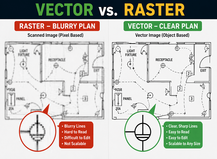
Most electrical contractors receive drawings from engineers and designers as scanned copies. Those scanned copies are raster images — essentially photographs of the drawing, made of pixels. They render beautifully in any standard PDF viewer. But auto-count software is not reading a picture. It is reading geometry. And when the geometry isn’t there — when all you have is a photograph — the software is guessing. And guessing is not good enough when your bid is on the line.
Understanding the difference between vector and raster drawings — and being able to identify which one you have before you start a takeoff — is one of the most practical things you can do to improve your auto-count results. Let me break it down.
What Is a Vector PDF?
A vector PDF is built from mathematical objects — lines, paths, curves, and points defined by coordinates and equations rather than pixels. When an engineer exports a drawing from AutoCAD or Revit as a true vector PDF, the software writes the geometry of every line, every arc, and every symbol as a set of mathematical instructions. Auto-count tools read those instructions directly.
- Precise geometry: Auto-count algorithms track the underlying math, not a visual approximation. The result is nearly perfect symbol matching because the software is reading exact coordinates, not interpreting a picture
- Flawless text recognition: Text exists natively in a vector file — no optical character recognition (OCR) is needed. Software can instantly read panel tags, equipment labels, and circuit numbers without interpretation errors
- Snappable symbols: Software can lock onto the exact center or boundary of every symbol because the geometry defines it precisely. False positives and missed counts drop dramatically
Vector is definitively the best format for auto-count tools — including Best Bid, Bluebeam, Revu, and Procore. If you can get vector drawings, always get vector drawings.
What Is a Raster PDF — And Why It Causes Problems
A raster PDF is, at its core, a photograph of a drawing. It is made of pixels — tiny colored squares arranged in a grid. When you zoom in close enough on a raster PDF, you will see the image degrade into individual pixels.
Auto-count software does not read pixels the same way it reads geometry. It has to interpret them. And interpretation introduces error.
- Pixel distortion: A clean, crisp symbol drawn in CAD becomes a collection of jagged pixels when scanned and saved as a raster image. Symbol edges that appear smooth on screen become imprecise at the pixel level, causing auto-count to miss matches or generate false positives — especially when resolution varies across a drawing set
- Artifact interference: Scanned drawings carry background noise — paper texture, smudges, fold lines, and compression artifacts from the scanning process. That noise distorts the symbol signature the software is trying to match, causing the auto-count to fail or require extensive manual correction before the count is usable
Raster PDFs are the source of the vast majority of auto-count frustration in the field. The tool is not broken. The drawing type is wrong.
Where Raster Drawings Come From
Most raster drawings that electrical contractors receive start as physical paper — full-size blueprint sets printed and used in the field, or older drawing packages stored in paper archives. When those drawings need to be shared digitally, they go through a wide-format scanner. The output is a TIFF, a flat PDF, a JPEG, or a PNG. Every one of those formats is a raster image.
These files look fine on screen. A 300 DPI scan of a clean blueprint looks sharp and readable in any PDF viewer. But it is still a picture of a drawing, not a drawing. And auto-count tools are built to read drawings, not pictures of drawings.
How to Check Whether Your Drawing Is Vector or Raster
Before you start any auto-count takeoff, run these two quick tests. It takes two minutes and saves hours of frustration.
- The Zoom Test: Open the PDF and zoom in as far as you can on a circle or a diagonal line. If the edge stays perfectly sharp at any zoom level — you have a vector file. If the edge turns jagged, blurry, or pixelated as you zoom in — you have a raster file
- The Text Test: Try to click and drag to highlight a word or a number in the drawing. If you can select individual characters and highlight specific text — you have a vector file. If clicking and dragging selects the entire page as a single image block — you have a raster file
Run these tests before every auto-count takeoff. Know what you are working with before you commit time to a process that may not work with your drawing type.
| 🔗 Best Bid Resource: |
| Continue Reading 👉 Guided Link: Post 7 — How to Get True Vector Drawings from AutoCAD and Revit 👉 Guided Link: Post 4 — AI Is a Tool, Not an Estimator 👉 Guided Link: Post 8 — The Two AI Auto-Count Models Every Electrical Estimator Should Know |