Understanding Stub Ups: Key to Effective Electrical Estimation

Electrical estimation involves accurately calculating the materials, labor, and time required for electrical installations. Among the various components of an electrical system, stub ups are often overlooked, despite their critical role in ensuring the system functions efficiently and meets code requirements. Let’s take a closer look at stub ups, their importance, and how to effectively estimate their requirements.
What Are Stub Ups?
Stub ups refer to raceways or conduits installed from an electrical box to above an accessible ceiling. They are commonly used in installations where cables or conductors will be pulled through the conduit at a later stage. This temporary installation allows other trades to finish their work while preparing the system for future electrical wiring. These raceways are typically installed with an open end, often covered with a bushing to protect the edges, and a pull wire is placed inside for future use.
Common Materials Used for Stub Ups: Stub ups are often constructed using ¾” EMT (Electrical Metallic Tubing), a standard conduit material known for its flexibility and durability. It’s usually installed from an electrical box with a plaster ring to above a dropped ceiling, where the open end is capped with a bushing.
Purpose of Stub Ups: Stub ups are primarily used to facilitate the future installation of electrical wiring. The raceway remains empty until the cables are pulled through during later phases of the project. By leaving the raceways in place with pull wires, electricians can install the necessary conductors when needed, ensuring a smoother and faster final installation process.
Benefits: Stub ups are a cost-effective and efficient solution for providing a pathway for future wiring. Since they are installed during earlier construction phases, they save significant time during the final wiring process and reduce the need for additional installations. They also ensure compliance with electrical codes by keeping the raceways in place for later use.
Key Considerations for Estimating Stub Ups
When it comes to estimating stub ups, accuracy is essential. The materials and labor involved are relatively straightforward, but failing to account for the specifics can lead to costly mistakes. Estimators need to consider several important factors:
Reviewing the Electrical Symbol Schedule
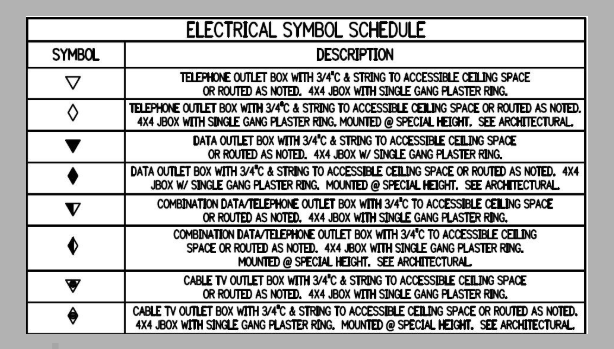
The first step in estimating stub ups is reviewing the Electrical Symbol Schedule. This schedule contains the standard electrical symbols used to represent various components of the electrical system, including raceways, outlets, and conduit types. Understanding these symbols helps in correctly identifying the requirements for stub ups, ensuring that no component is missed during estimation.
Electrical Symbols: The schedule will typically show various types of raceways, boxes, and other related components. While there may be 8 different symbols for raceways, all of these symbols generally require the same amount of material and labor for installation. It’s important for the estimator to recognize that, while the symbols may look different, the overall effort needed to install each type of raceway is relatively consistent.
Grouping Symbols for Simplified Estimation: Some estimators prefer to group all 8 symbols into one takeoff, while others may separate them based on specific categories like telephone, data, or cable systems. In many cases, especially when conductors and jacks are not being installed, combining them into a single takeoff can save time and ensure consistency across the project.
Creating an Assembly for Stub Up Installation
Once the relevant symbols are identified, the next step is to create an assembly of items required for each stub up installation. This includes the materials needed to install each raceway and ensure proper functionality:
Materials for Each Stub Up
10’ ¾” EMT Conduit: This is the standard length of conduit needed for each stub up.
1-4×4 Box with Bracket: Essential for securely mounting the raceway to the structure.
1 Plaster Ring: This provides a mounting point for the raceway.
2/3/4” Straps: Used to secure the raceway to the ceiling structure.
2-3/4” Connectors: Necessary for connecting the raceway sections.
1-3/4” Plastic Bushings: Installed at the open ends of the raceway to protect cables and wiring during installation.
4 Tek Screws: These screws are used for securing the boxes and brackets in place.
Groupings Based on Electrical System Components
In some cases, stub ups are grouped based on their function within the electrical system. For example, telephone, data, or cable systems each require specific considerations for their installation and materials.
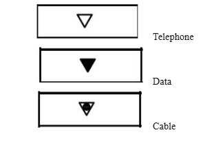
Grouping by Function: If the stub up is part of a telephone, data, or cable system, it’s important to ensure that the conduit and box used are suitable for each application. The materials and installation techniques may vary slightly depending on the requirements of each system, although the basic process remains similar.
When to Combine Symbols: For estimators not responsible for installing conductors and jacks, it’s recommended to combine all symbols into one takeoff. This simplifies the estimation process and avoids overcomplicating the material count. When the work involves only the raceway and box, the process becomes much more streamlined.
Feeder Takeoffs

Another essential component of electrical estimation is the feeder, which refers to the conductors that transport electricity from the power supply source to the final branch circuit overcurrent device. Properly estimating feeders is just as important as accurately estimating stub ups, and it involves several critical considerations.
What is a Feeder?
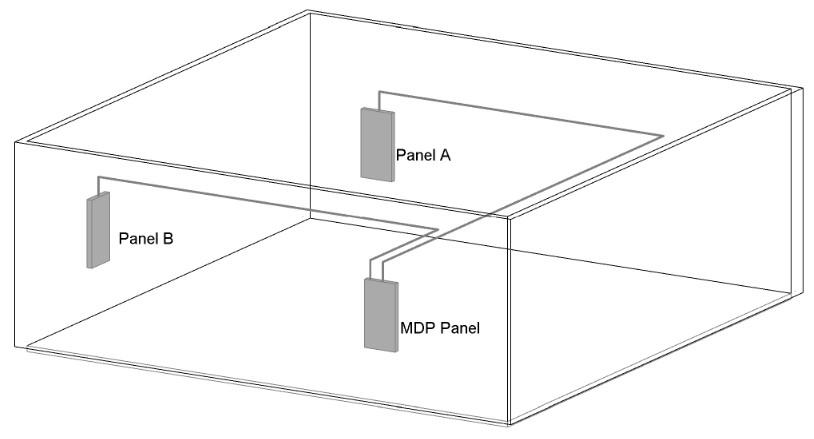
A feeder is defined as a circuit conductor that connects the power supply to the final overcurrent device, often found in distribution panels. It serves to carry electrical current from a central point, such as the main distribution panel (MDP), to smaller panels or load centers.
Common Feeder Applications: In the example of a typical electrical system, feeders transport electricity from the MDP to Panel A and Panel B. These conductors are vital for ensuring that each area of the building has access to the required power for its equipment and lighting.
Feeder Runs: Feeder runs often deviate from the shortest possible distance. The raceway may need to follow the building’s layout, running at angles, over or under obstacles, and through other structures. These extra distances must be factored into the estimate to ensure the proper length of conduit and wiring is accounted for.
Accurately Measuring Feeder Lengths
Measuring the correct length of the feeder is one of the most critical steps in estimating, especially since the raceway is rarely installed in a straight line. Estimators need to consider the total length of the raceway, including any bends or deviations caused by obstacles.
Factors Affecting Feeder Length
Building Layout: Feeder conduits often need to follow the building’s structure, which means accounting for any deviations from a straight path.
Risers: The length of the raceway must also account for any risers required for overhead or underground runs.
Terminations: Additional length is needed at both ends of the raceway to account for terminations and the connections to equipment or panels.
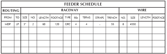
Feeder Takeoff Sheets
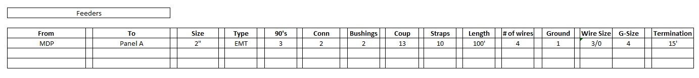
A detailed feeder takeoff sheet helps estimators track all the necessary materials and dimensions for the installation. The sheet includes:
Size of Raceway: The exact size of conduit required for each feeder run.
Number of 90-degree Bends: Any necessary elbows or turns along the route.
Materials: Record the connectors, bushings, couplings, and straps needed.
Wire Requirements: List the number of wires, their sizes, and extra length for terminations.
Checklist for Feeder Takeoffs
When estimating feeders, it’s essential to consider the following:
Conductor Type: Aluminum or copper conductors may be required based on the system’s needs.
Raceway Material: EMT, PVC, or rigid raceways each have different cost implications and installation requirements.
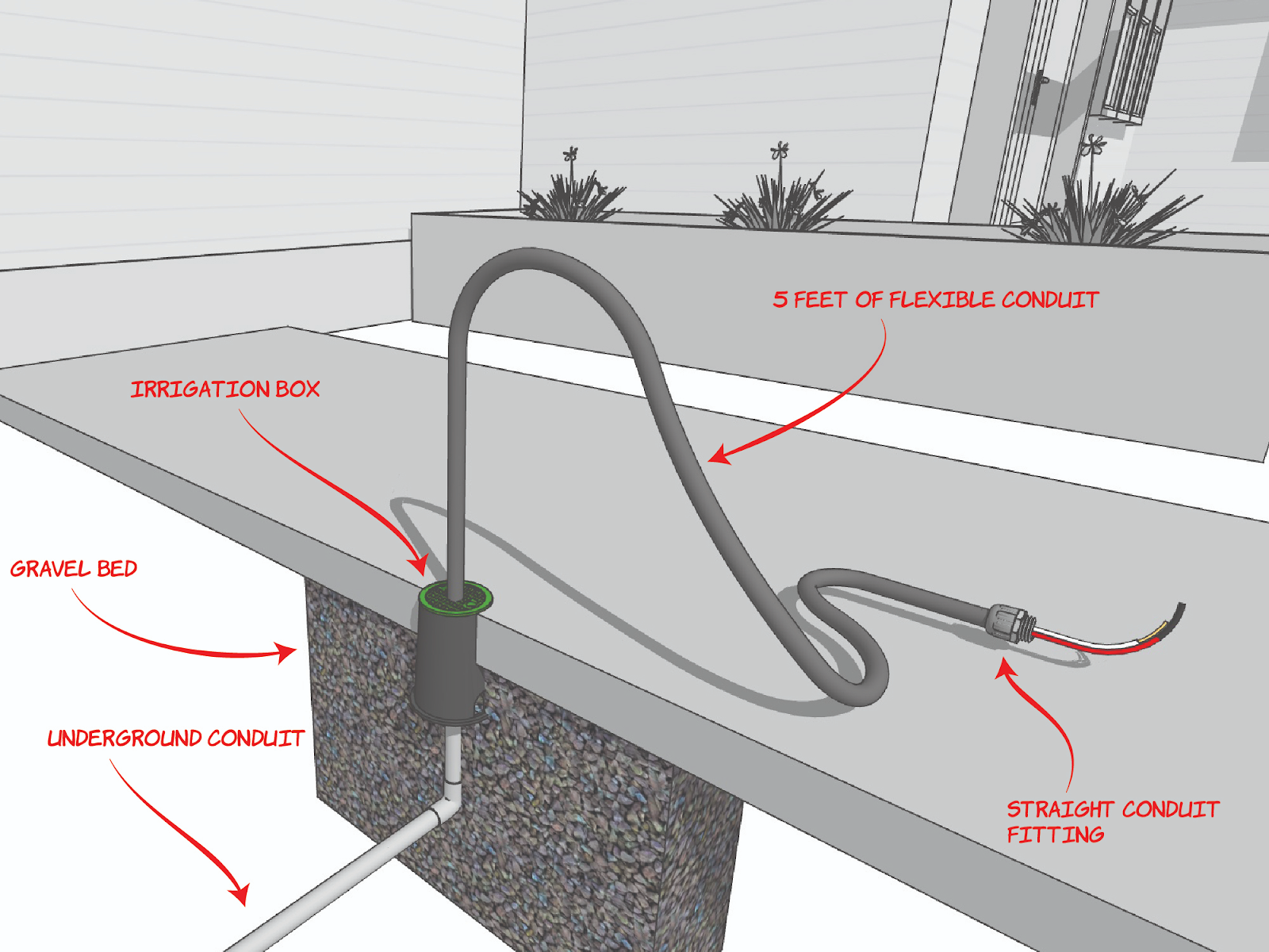
Underground Requirements: For underground feeders, ensure that proper underground raceways and PVC or rigid 90-degree elbows are used to protect the wiring.
Parallel Runs: Determine whether the feeder will consist of a single run or multiple parallel runs, which can affect the material count and cost.
Feeder Estimation
Estimating feeders accurately is crucial, not just to determine material quantities but also to estimate labor costs and time effectively. The complexity of feeder estimation often lies in the extra distance required to reach destination panels, the type of raceway and conductors, and the presence of any underground or overhead runs.
Why Precision Matters in Feeder Estimation?
The feeders connect the power distribution panels (MDP, Panel A, Panel B, etc.) to individual circuit breakers or branch circuits, meaning errors in measurement can affect not only the installation but the overall electrical system performance. Incorrectly estimated feeder lengths or materials can lead to excessive costs, project delays, or compliance issues with the NEC (National Electrical Code).
Considerations for Efficiency: When estimating feeders, it’s essential to minimize excess material costs without compromising safety or functionality. Overestimating the length of raceway or wire needed is common, especially when not accounting for the angles and bends necessary in most building layouts. Conversely, underestimating can lead to material shortages that delay installation and create expensive change orders. By measuring carefully and considering the unique needs of the building and installation environment, you can ensure both cost-effectiveness and project efficiency.
Advanced Feeder Estimation Tools: Many estimators now turn to software solutions for more advanced takeoff and estimating techniques. Digital tools like DigiCount Takeoff Pro offer automatic measurement capabilities, which can help speed up the process and ensure greater accuracy. These tools can automatically calculate lengths, bends, and connectors required for feeder installation based on input specifications.
Estimating Labor for Stub Ups and Feeders
Labor costs represent a significant portion of electrical installation expenses, and accurately estimating the required labor hours for stub ups and feeders is essential for keeping the project within budget. Labor estimation for these components varies based on the complexity of installation, the number of bends in the conduit, and the overall route length.
Labor for Stub Ups
Stub ups involve simple yet critical installation steps. The labor required for stub ups is generally straightforward, but estimators should account for the time it takes to measure, cut, and install the raceway, as well as to securely attach the boxes, brackets, and straps.
Common Labor Tasks
Measuring and cutting EMT conduit to the required lengths.
Installing and securing the 4×4 boxes with brackets.
Mounting plaster rings and attaching connectors.
Running pull wires through the raceway for future cable installation.
Labor Efficiency Tips
While the installation is simple, grouping stub up installations together can significantly reduce labor costs. Installing multiple stub ups in the same area reduces setup time and streamlines the labor process.
Labor for Feeders
Estimating labor for feeder installation is more involved and requires careful consideration of the complexity of the installation. Feeders typically require bending the raceway, handling larger conductors, and possibly working in hazardous or difficult-to-reach locations.
Tasks Involved
Bending Raceways: Conduit needs to be bent at appropriate angles, and estimators should account for the time it takes to make and install 90-degree bends. Some feeders may require custom bending, which takes more time and effort.
Pulling Wires: The labor required to pull wires through the raceway is often the most time-consuming part of the process. The larger the feeder size and the longer the distance, the more labor is involved.
Underground Feeder Installation: Installing feeders underground requires additional labor to trench the ground, lay the raceway, and ensure the system is properly protected from external elements. Estimators should account for labor costs related to excavation, backfilling, and any concrete or material needed for protection.
The Role of Code Compliance in Estimating Stub Ups and Feeders
Electrical installations must meet local and national standards, ensuring safety, reliability, and long-term functionality. Both stub ups and feeders must adhere to NEC guidelines, which influence the estimation process.
Stub Up Code Compliance
For stub ups, several NEC requirements must be considered to ensure the installation is compliant and safe:
Conduit Material: The conduit used for stub ups must meet the required specifications. EMT (Electrical Metallic Tubing), commonly used for stub ups, is a lightweight and flexible conduit that can easily be bent. However, estimators must verify that EMT is the correct material for the environment, as specific installations may require more robust materials like rigid conduit.
Bushing Requirements: The open ends of the conduit must be protected with plastic bushings to prevent damage to the wires that will be pulled through in the future. This is crucial for ensuring that the raceway meets safety standards.
Minimum Height of Stub Ups: The NEC specifies minimum height requirements for stub ups, which ensure that the raceway extends high enough above the ceiling to allow for easy cable pulling and future modifications. Estimators should account for this height when calculating material costs.
Feeder Code Compliance
Feeders must also meet strict code requirements to ensure safe power distribution across a building or facility. Key code compliance aspects for feeders include:
Correct Sizing: The raceway and conductor sizes for feeders must meet the load calculations specified in the NEC. Estimators should carefully review electrical drawings to ensure they select the correct feeder sizes to handle the expected electrical load.
Raceway Protection: Underground feeders require special considerations to protect the raceway from physical damage. According to the NEC, conduit used for underground feeders must be PVC or rigid conduit for added durability.
Overcurrent Protection: Every feeder circuit must be protected by an overcurrent protection device, such as a breaker or fuse. The NEC specifies the correct overcurrent protection ratings for each type of feeder, which must be factored into the estimation.
Conclusion
In electrical estimation, accuracy and efficiency are paramount to ensuring a successful project. Stub ups and feeders play vital roles in the electrical system, and their proper estimation is crucial for material and labor cost management. By understanding the specific requirements, adhering to code regulations, and using advanced tools, estimators can optimize the estimation process, saving both time and money while ensuring safety and compliance.
Ready to win more bids with accurate estimates? Get started with BestBidEstimating today and streamline your electrical project estimates for success!
Continued in Electrical Estimating for HVAC Systems: A Comprehensive Guide


")