Electrical Estimating for HVAC Systems: A Comprehensive Guide

When estimating electrical projects, HVAC systems represent a critical and often complex part of the job. Almost every project requires heating, ventilation, and air conditioning (HVAC) work, which necessitates detailed planning and accurate calculations. In this blog, we’ll walk you through the essential steps, considerations, and best practices for accurately estimating electrical components for HVAC systems, ensuring your bids are competitive and profitable.
Understanding HVAC Electrical Requirements
Before diving into your takeoff process, it’s vital to review the project specifications thoroughly. HVAC systems are not one-size-fits-all, and their electrical requirements can vary significantly based on the type of equipment and the project’s scope. Start by gathering the following critical information:
1. Voltage and Phase
Determine the voltage and phase requirements of the HVAC units. This information will guide your selection of disconnects, conductors, and other components.
Consider any voltage adjustments or transformers that may be required to meet the project’s needs.
2. Disconnects
Check whether the units require fusible or non-fusible disconnects.
Verify the NEMA configuration (e.g., NEMA 1, NEMA 3R, or NEMA 12).
Identify whether the disconnects need to be heavy-duty or standard-duty.
Determine if special fuses or rejection clips are required.
Note if the disconnects will be located indoors or outdoors, as this impacts material selection.
3. Controls and Starters
Establish who is responsible for furnishing controls, cables, and starters. Some projects include these as part of the equipment, while others require separate sourcing.
Confirm compatibility between the control systems and the HVAC units, especially for large or custom setups.
4. Included Components
Confirm if disconnects and GFCI receptacles come pre-installed on the units. This can save time and reduce costs.
Check if the units come with integrated surge protection or require additional external protection.
Evaluate if mounting brackets or hardware for the disconnects are included.
Identifying HVAC Equipment Types
The type of HVAC equipment being installed will impact the electrical requirements. Reviewing the HVAC equipment schedule can help you determine the specific units and their electrical needs. Common types of HVAC systems include:
Split Systems: These consist of an air handler and a condensing unit. Split systems are common in residential and smaller commercial projects.
Package Units: These units combine all components into one location, simplifying installation and reducing space requirements.
Gas Packs: Typically require less ampacity due to their reliance on gas for heating.
Electric Units: Require more ampacity, especially for heating elements.
Heat Pumps: Have the highest ampacity requirements, particularly in colder climates where they function as primary heating sources.
Boilers and Chillers: Often used in large commercial applications, requiring specialized wiring and control systems.
VAV Valves, Air Handlers, and Ductless Split Units: Require specific wiring and control setups, often including communication cabling for centralized systems.
Fan Schedule
In addition to the HVAC equipment schedule, review the fan schedule. It will provide details about the voltage, phase, and any special wiring requirements for the fans associated with the HVAC system.
Check if variable speed drives (VSDs) are required for fans, as they can impact the overall electrical design.
Verify the location of fans and their accessibility for installation and maintenance, which may influence conduit runs.
Creating a Disconnect Schedule

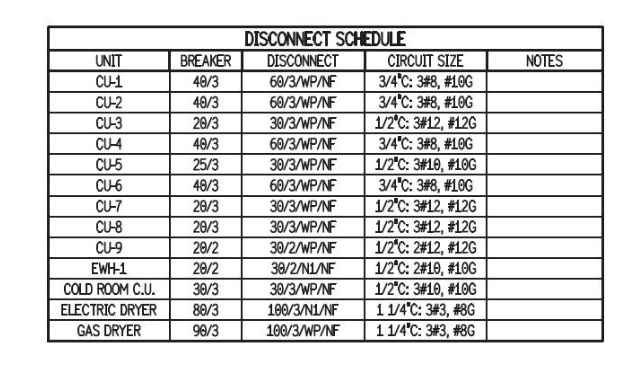
A disconnect schedule is a valuable tool that consolidates all the necessary information for estimating. If the project engineer doesn’t provide one, you should create it yourself. A well-organized disconnect schedule serves as a central repository of critical data and simplifies calculations. A typical disconnect schedule includes the following details:
Unit Name: Identify each unit by name, such as CU-1, CU-2, or CU-3. This ensures clarity when cross-referencing equipment and electrical plans.
Voltage and Phase: Document the voltage and phase requirements for each unit. This is essential for selecting appropriate conductors, disconnects, and protective devices.
Disconnect Type and Size: Specify whether the disconnects are fusible or non-fusible and provide the required amperage ratings. Including this information upfront helps eliminate potential mistakes during procurement.
Distance from Power Source to Unit: Measure and record the distance from the power source to each HVAC unit. Add this detail to the notes section for easy access when calculating conduit and conductor requirements.
Special Installation Notes: Include additional considerations, such as weatherproofing for outdoor installations or seismic requirements for areas prone to earthquakes. Other details might involve heat-resistant materials or tamper-proof features.
By organizing this information in one place, you’ll streamline your estimating process and reduce errors. A disconnect schedule not only provides clarity but also helps ensure compliance with project specifications. For example, if CU-1, CU-2, and CU-3 share the same specifications, you can calculate materials and costs for one assembly and multiply by three for quick results. Additionally, documenting distances in the notes section simplifies labor and material calculations later in the process.
For larger or more complex projects, consider enhancing your disconnect schedule with supplemental details such as:
Coordination with Other Trades: Note potential overlaps with mechanical or structural systems that could impact the placement of disconnects.
Future Expansion Needs: Include provisions for possible upgrades or additional units in the future.
Control Integration: Ensure compatibility between disconnects and automated control systems for centralized HVAC management.
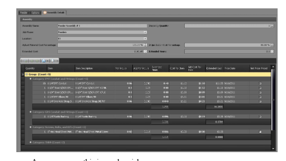
Assemblies for Liquid-Tight Conduit
For each HVAC unit, you’ll need to create an assembly for liquid-tight conduit (also known as sealtight). Liquid-tight conduit is commonly used for HVAC installations due to its flexibility and resistance to moisture, making it ideal for protecting wiring in outdoor or exposed environments. Here’s an example of a standard assembly:
6 Feet of Liquid-Tight Conduit: Size as required by project specifications.
2 Liquid-Tight Connectors: Sized appropriately for the conduit.
16 Feet of Grounding Conductor: Ensure compatibility with local grounding requirements and the size of the electrical load.
16 Feet Per Current-Carrying Conductor: Sized as needed for the HVAC unit’s ampacity.
1 Strap: For securing the conduit in place.
5 Screws: For mounting straps and connectors securely.
Heat-Shrink or Sealing Tape: To provide weatherproof protection for outdoor installations.
For projects with multiple HVAC units, such as CU-1, CU-2, and CU-3, simply multiply the quantities by the number of units. For example, calculate the material and labor costs for one assembly and multiply by three. This approach not only saves time but also ensures consistency across similar installations.
Additional Considerations
Routing Challenges: Account for additional conduit lengths when routing around obstructions, through tight spaces, or across large distances. Avoid underestimating material needs by performing a thorough site review.
Weatherproofing Requirements: Ensure that all conduit and connectors meet project-specific standards for outdoor installations, especially in harsh climates.
Support and Securement: Properly secure liquid-tight conduit with straps and supports to prevent sagging or damage over time. Pay close attention to code requirements for spacing and support placement.
By systematically assembling and documenting materials, you’ll create a comprehensive takeoff that is both accurate and efficient.
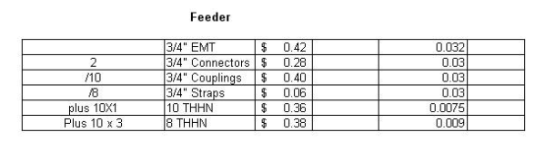
Feeder Portion of the Circuit
The next step in the HVAC takeoff is the feeder portion of the circuit. Feeders are critical for delivering power from the distribution panel to HVAC units, and they require careful planning and precise calculations. Follow a similar approach as you did for the disconnect and liquid-tight assemblies to ensure accurate material and labor estimates.
Steps for Feeder Takeoff
Measure Total Length of Raceways: Include horizontal runs, vertical rises, and any additional lengths required for terminations. Accurately measuring these distances ensures that you don’t underestimate the amount of conduit or conductors needed.
Create a Feeder Assembly: Develop an assembly that includes all required materials, such as conduits, conductors, connectors, and supports. For example:
Conduit (PVC, EMT, or GRS, as specified).
Conductor type and size (e.g., THHN).
Pull boxes or junction boxes for long runs.
Multiply Material Quantities: Determine the number of feeder runs required and multiply the material quantities by this number. Document any unique feeder characteristics, such as varying conduit sizes or conductor ratings.
Consider Voltage Drop: For long feeder runs, calculate voltage drop and adjust conductor sizes accordingly. This ensures compliance with code requirements and prevents equipment malfunctions.
Include Consumables: Account for items like pulling lubricant, fish tape, and other consumables required for installation.
For example, if you have three feeder runs with identical specifications, calculate the material and labor costs for one run and multiply by three. Always include allowances for bends, offsets, and terminations when estimating conductor lengths.
Best Practices for Feeder Installation
Plan for Future Expansion: Include spare conduits or oversized feeders for potential future upgrades.
Minimize Voltage Drop: Design feeders to maintain efficiency by minimizing voltage drop, particularly in high-power installations.
Coordination with Other Systems: Ensure feeders do not conflict with plumbing, structural supports, or other building systems.
By following these steps, you can ensure a reliable and cost-effective design for HVAC feeders.
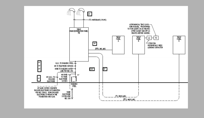
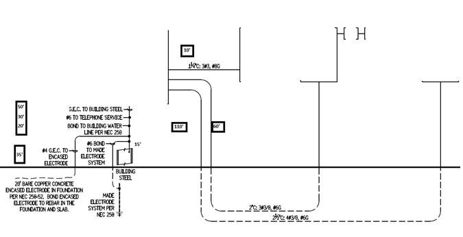
Using the One-Line Diagram
The one-line diagram is an essential tool for electrical estimating. It provides a simplified representation of the electrical system and helps you identify the gear, panels, and connections required for the project.
Key Elements to Note
Gear Names: List all gear mentioned in the diagram, such as MDP (Main Distribution Panel), Panel A, Panel B, and Panel K.
Specifications: Document the voltage, phase, NEMA configuration, AIC rating, mounting style (surface or flush), and any special requirements (e.g., seismic engineering, digital readouts, remote monitoring).
Feeder Paths: Trace all feeder paths and record distances to ensure accurate takeoffs.
When requesting a gear quote, include the panel schedule and specification sheets to ensure accurate pricing from suppliers. Highlight any custom features or deviations from standard designs.
Mounting the Gear
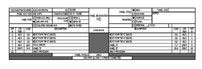
Take note of any special requirements for mounting panels and gear. Some projects may require seismic engineering, which can significantly impact costs. Use the panel schedule to identify mounting hardware needs. For example:
MDP Mounting Hardware
6 × ½” lead anchors.
6 × ½” bolts.
6 × ½” fender washers.
Weatherproof gaskets for outdoor installations.
Panel A and B Mounting Hardware

8 × ⅜” lag screws.
8 × ⅜” fender washers.
Brackets or stands for elevated mounting, if required.
Panel K Mounting Hardware
4 × ½” lag screws.
4 × ½” fender washers.
Estimate the costs for mounting hardware and include them in your bid as either a detailed breakdown or a miscellaneous allowance. If seismic requirements apply, consult with structural engineers to confirm hardware specifications.
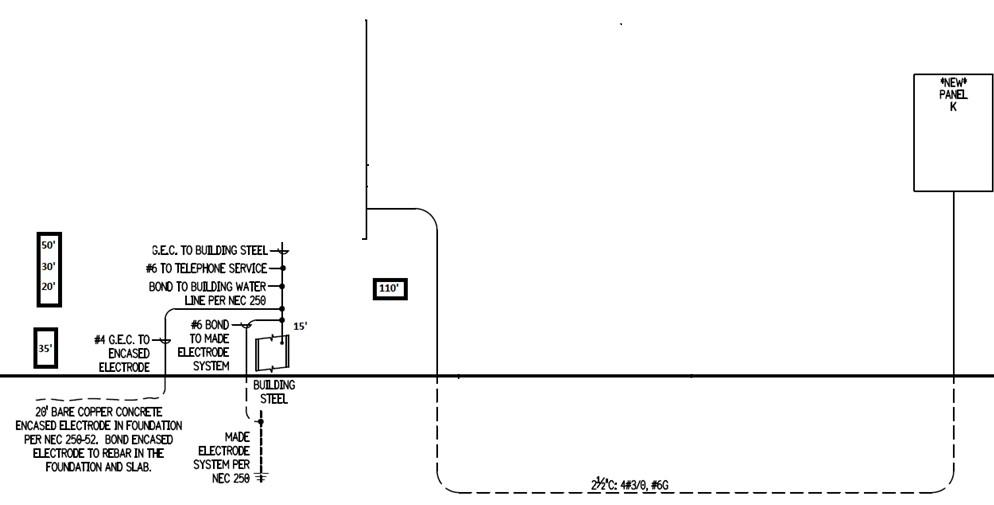
Estimating Feeders
Break the feeder installations into smaller sections to simplify the process. For each feeder:
Measure the Distance: Include horizontal runs, vertical rises, and additional lengths for terminations.
Select the Materials: Choose the appropriate conduit (e.g., PVC, EMT, or GRS) and conductors (e.g., THHN).
Calculate Conductor Lengths: Add up all distances, including allowances for risers, bends, and terminations.
Include Junction Boxes: Account for junction boxes and pull points if required for long or complex runs.
For example, for a feeder from MDP to Panel B:
Horizontal distance: 60 feet.
Vertical rise: 10 feet.
Bends: 6 feet.
Termination allowance: 15 feet.
Total conductor length: 91 feet.
Repeat this process for each feeder identified in the one-line diagram. Ensure you include all accessories, such as conduit clamps and supports.
Grounding Requirements
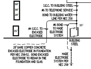
Grounding is a crucial aspect of HVAC electrical systems. Typical grounding requirements include:
Grounding Electrode Conductor: Connects to building steel (e.g., 50 feet of 2/0 bare copper).
Connection to Water Line: Requires 20 feet of 2/0 bare copper and a water pipe grounding clamp.
Ground Rods: Include the rods, clamps, and conductors needed for proper grounding.
Additional Grounding Requirements: Bonding jumpers for mechanical equipment and grounding connections for communication and control systems.
Document all grounding materials and labor in your estimate to ensure compliance with code requirements. If using ground enhancement materials or exothermic welds, include these in your calculations.
Finalizing the Estimate
Once you’ve completed the takeoff for all HVAC-related components, compile the following:
Material List: Include all items identified during the takeoff (e.g., conduits, conductors, disconnects, mounting hardware).
Labor Hours: Assign man-hours to each material item based on installation requirements.
Total Costs: Calculate the total material and labor costs, including overhead and profit.
Proposal Preparation: Ensure your bid includes a clear scope of work, exclusions, and any special notes (e.g., seismic requirements, unique mounting conditions).
Cross-Check: Review all specifications and drawings to confirm nothing is overlooked. Validate pricing with suppliers for any large or custom orders.
Using electrical estimating software like BestBidEstimating can streamline this process by automating calculations and organizing your data more efficiently. Additionally, regularly updating your material and labor databases ensures your estimates reflect current market conditions.
Conclusion
Estimating electrical work for HVAC systems requires attention to detail, accurate measurements, and thorough documentation. By following the steps outlined in this guide, you can create reliable estimates that account for all materials, labor, and project-specific requirements. This approach ensures your bids are competitive while maintaining profitability and meeting client expectations.
Remember, practice and experience will refine your estimating skills. Over time, you’ll develop efficient workflows and build confidence in tackling even the most complex HVAC projects.
Continued in Mastering Man-Hours: The Key to Accurate Electrical Estimating